Updated - September 8, 2022 - Copyright - Ralph Gibson - 2014

The CNC Mill
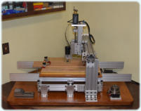
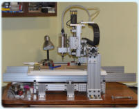
One of my favorite tools I have to tinker with is a CNC Mill that I designed and built
as shown below. This is a hybrid tool built up and based on two very different
system parts. The “X” axis was built using aluminum extrusions and hardware
from OpenBuilds. The “Y” and “Z” axis were built using aluminum extrusions and
hardware from 80/20 Inc. Most components used in the design were purchased
from CNC Router Parts, Automation Technology, Inc., and McMaster-Carr.
The original mill with +48VDC, 400W air cooled spindle
is shown on the left. On the right, is the mill upgraded
with a 240VAC, 1,500W ER11 water cooled spindle. The
new spindle is driven by a 2,200W VFD which provides
very accurate speed adjustment. The mill was designed
to be somewhat different than most examples I’ve seen.
The “X” table moves side to side, instead of the “Y”
crossbar moving. Mostly because I have some cabinets
above the mill that the “Z” axis would hit if the “Y” crossbar moved. For manual operations on each axis, I
used handles from Taig Tools that were used on the Taig micro-mill that I own as I find them very
comfortable to use. Brass adapters for the Taig handles I turned on my Taig micro-mill for the CNC mill.
For the CNC mill, I used 1/2”-10TPI ACME stainless steel threaded rod for the drive on each axis, that I
purchased from McMaster-Carr. With the 200 step per revolution stepper motors and 10TPI threaded rod,
the mill has a 0.0005” resolution per step. I’ve found it to be extremely accurate and repeatable in use.
I use VCarve-Pro from Vectric to generate gCode to drive the mill, a Gecko G540 4-axis controller to drive
the stepper motors, and Mach3 CNC Control Software from ArtSoft to drive the Gecko controller. I
purchased the Gecko G540 controller with a 48V, 12.5A power supply, and chassis as an enclosure set
from Automation Technology, Inc. (KL-G540-48). Usually I draw up whatever I’m going to mill using Xara
Designer Pro X9 and export the drawing as a .AI file, which I can then import into VCarve-Pro.
I have fabricated limit switch mounting blocks but haven’t installed those as yet. A vacuum pickup head
and rotary table, have been designed and tested, and work great. The mill has about 18” travel in the “X”
axis, 15” travel in the “Y” axis, and 5” travel in the “Z” axis. Once I install the limit switches the travel will
be reduced by about one inch or so in each axis.
Home Milling Project:
A home milling project I did in early 2016 was to fabricate a base for a bathroom light fixture. The
electrical box for the light was installed before the cabinets and granite counter top were added.
Unfortunately, due to the cabinet layout, the sink couldn’t be centered under the outlet box, so there was
a 4” offset between the electrical box and the center of the sink as shown in the left photo.
I designed a lamp base using Xara Designer Pro X9 as shown, exported the design as an Adobe Illustrator
file, and then imported the file into VCarve-Pro. The mill parameters were set in VCarve-Pro and the
gCode files needed to drive the CNC mill were generated.
The bathroom lamp base was milled out of 3/4” Red Oak, 12-3/4” wide by 9” high. The width was set so
when the electrical box was covered, the center of the lamp was over the center of the sink and mirror.
The hole through the lamp base for the wires to pass through lined up with the left side of the electrical
box. The lower right photo shows the finished base mounted on the wall with the lamp installed.
Milling Projects for Work:
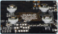
An example of some milling I’ve done for work is shown here. On a printed circuit board
(PCB), some parts were placed too close to the mounting holes for an optional socket to be
mounted. So I milled some small standoffs out of FR4 PCB material to clear the parts on
the board, so the socket could be used. The image of the standoffs shown on the left side
is the VCarve-Pro milling simulation. The photo on the right side was taken
with standoffs mounted on the board supporting the socket hold down nuts.
We identified a need for the standoffs in the early afternoon, and the next
morning I was able to bring in 27 milled parts to support up to six boards. It’s
very handy to have the ability to quickly turn a limited number of small parts
when needed.
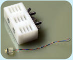
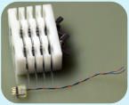
Another example of a work project is shown at right. The software
development group I formerly worked with, needed small cables to
gain access to serial ports on their development platforms.
However, the 30ga wires attached to the pins on the 2mm headers
were very easy to break if not supported.
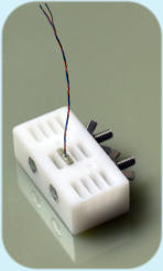
I had an older mold that I fabricated on my Taig manual mill, that
allowed a two part epoxy mix to cast heads for two cables at a
time. However, the team needed to fabricate many cables and
casting only two at a time tended to be pretty tedious. Shown
here is a new mold that I fabricated out of HDPE on my CNC mill
that allowed up to twelve cable heads to be cast at the same time.


